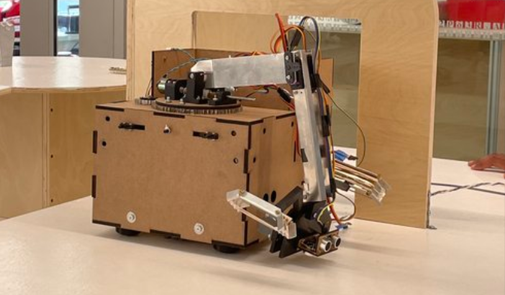
Autonomous Treasure Retrieval Robot
A robot designed to navigate an obstacle course while retrieving objects for 2022 Annual Engineering Physics Robotics Competition
Learn moreFor my internship in Summer-Fall 2023, I worked on building an inverted pendulum. The goal of this project is to design a real world real-time control system to evaluate the performance of In-ConcReTes, a Byzantine Fault Tolerant key-value store.
I worked on code for the In-ConcReTes protocol. This has included software integration of the protocol with the pendulum system and adding some functionality. Recently I worked with the network stack for the protocol to add a reconnection feature that allow failed nodes on the distributed network to reconnect with peers.
This phase has allowed me to learn more about C++, with features such as template programming, working with TCP, threading and timing on Linux.
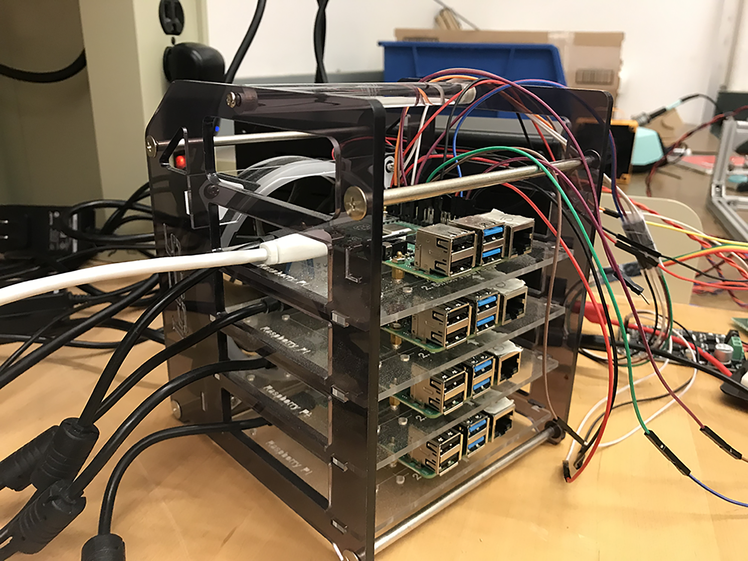
I developed all the project firmware for the pendulum in C++ for a Raspberry Pi and for the Bluepill (STM32F103C). This included UART and I2C communication code, sensor filtration, motor control code, PID control and real-time telemetry interfaces so far.
In writing the firmware, I learned more about the I2C communication protocol and how Linux handles I2C communication through the SMBus interface. To create real time plotting, I learned more about the concept of pipes in Linux and how they can be used for interprocess communication so that I could communicate between the controller process to a separate plotting process in real time. I also experimented with developing firmware with FreeRTOS and STM32.
I am completed the controls for the pendulum to achieve balancing capabilities. This has involved modelling the physical system to get a better understand of system dynamics and learning more about the specific use cases for various controllers such as LQR and PID.
In learning about controls through some independent research, I developed a better understanding of how control systems can be characterized as controllable or uncontrollable and how we can use Matlab to analyze and simulate a control system. This has allowed me to have a more systematic approach in developing the controller for my pendulum.
To design and build the pendulum, I created a CAD model on OnShape as seen below. The design is largely inspired by an open-sourced pendulum design. Additionally, I sized and ordered appropriate mechanical and electrical components given the system specifications, built the structure and completed the electrical integration. Building the pendulum involved using 3D printers, laser cutters, soldering irons and other tools. The electrical integration phase included sizing the power supply, testing motor driver and various sensor circuits and planning wiring with modularity in mind.

A robot designed to navigate an obstacle course while retrieving objects for 2022 Annual Engineering Physics Robotics Competition
Learn more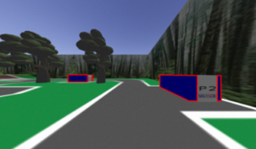
I worked to train a rover to drive around a simulated road while detecting license plates of nearby vehicles, avoiding pedestrians and other moving vehicles.
Learn more